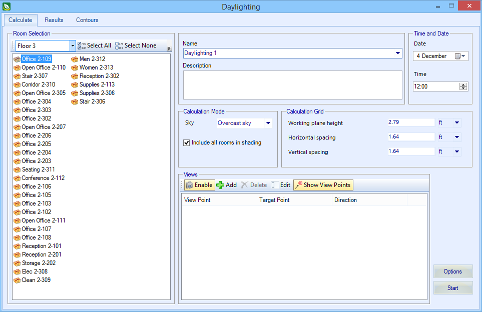
| Rooms Selection
|
Contains tools used to select the thermal zones
containing the rooms you want to include in daylighting calculations.
- Zones drop list -
Contains a list of all existing zones to select from. When a zone is selected,
the rooms it contains are listed in the rooms list panel.
- Select
All
- Selects all the rooms in the selected zone.
- Select
None
- Deselects all selected rooms.
- ... (Options) -
Drop menu contains options for displaying rooms with divisions (virtual walls).
- Rooms
Only - Sets rooms panel to display only room objects.
- Show
Divisions - Sets rooms panel to display only room division objects.
- Show
Divisions with Room - Sets rooms panel to display both room and
room division objects.
- Rooms panel - Lists
rooms and divisions based on selections made with the Room Selection tools.
|
| Name
|
Used to enter a name for the simulation, and to
select existing simulations.
|
| Description
|
Used to enter a description for the simulation.
|
| Time and Date
|
- Time - Used to
enter the date to simulate with Day/Month format. A pop up calendar is
available for selecting a date.
- Date - Used to
enter the time of day to simulate with Hour/Minute format. Up/Down arrows are
available to modify the hour and/or minute.
|
| Calculation Mode
|
- Sky - Sets the
sky conditions for the simulation. available choices are:
- Sunny with sun - The
sky distribution corresponds to the standard CIE clear sky condition with
additional direct illumination from the sun included. Expect very bright
patches due to direct illumination from the sun with relatively dark areas
where direct sunlight does not fall.
- Sunny without sun -
The standard CIE clear sky distribution without direct illumination from the
sun.
- Intermediate with sun
- Sky with intermediate conditions between the overcast and clear skies with
direct illuminance from the sun included.
- Intermediate no sun -
The CIE standard intermediate sky with illuminance distribution conditions
between the overcast and clear skies. Direct illuminance from the sun is not
included.
- Overcast sky - The
CIE Standard Overcast Sky, originally known as the Moon and Spencer Sky, was
devised to represent the luminance distribution observed for overcast skies.
Adopted as a standard by the CIE in 1955, this description is the one most
frequently used for illuminance modelling. In this model, the sky brightness
increases gradually with altitude from the horizon to the zenith, but it does
not vary with azimuth.
- Uniform sky - where
the sky illumination is completely uniform.
- Daylight factors
- Include
all rooms in shading - When on, all rooms are considered in the
daylighting calculation. When off, only the selected rooms are considered in
the daylighting calculation.
|
| Calculation Grid
|
- Working
plane height - Used to enter the height of the working plane above
floor level for each zone in the daylight simulation. The working plane height
is normally set at the average height of the top surface of the desks above the
floor. A typical value will be in the range 0.7-0.8 meters.
-
Horizontal spacing
- Used to divide up the working plane horizontally
when calculating illuminance. Larger values will speed up calculations but give
lower resolution in daylighting outputs. You should consider the size and
number of zones in the building when entering values. Fine horizontal spacing
causes the daylighting calculations to take a longer to complete. However,
coarse horizontal spacing in a small zone may not give a good enough
distribution.
-
Vertical spacing - Used to divide up the
working plane vertically when calculating illuminance. Larger values will speed
up calculations but give lower resolution in daylighting outputs. You should
consider the size and number of zones in the building when entering values.
Fine vertical spacing causes the daylighting calculations to take a longer to
complete. However, coarse vertical spacing in a small zone may not give a good
enough distribution.
Note: To maintain a
uniform grid across the working plane set the
Horizontal spacing
size the same value as the
Vertical spacing size.
|
| Views
|
Contains controls used to manage daylighting view
points to rooms in the model.
- Enable - When
on (button highlighted), selected view points are included in the daylighting
calculation.
- Add - Used to
add a view point. Clicking
Add temporarily hides the Daylighting
dialog, and prompts you to:
- Select room - Select a room in the model.
- Select view point - Identifies the location of the view
point with a data point.
- Select target point - identifies the direction and target
of the view point with another data point. A graphical vector symbol is created
to represent the view point.
After the target point is selected, the Daylighting dialog
is restored, and the new view point appears on the list (within the selected
room hierarchy). You can add as many view points as you want.
- Delete -
Removes selected view points from the list.
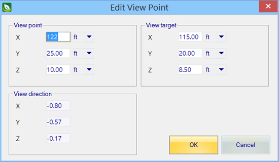
- Edit - Used to
modify existing view points. Clicking
Edit opens the Edit View Point dialog
which contains controls to modify the view point details.
Note: Can also
be opened by double clicking view points in the
Views table.
- View
point: X Y Z - Used to manually edit the coordinates of the view
point you established using the
Add tool.
- View
target: X Y Z - Used to manually edit the coordinates of the view
target you established using the
Add tool.
- View
direction: X Y Z - Used to manually edit the coordinates of the
view point direction you established using the
Add tool.
- OK - Saves all
changes, closes the dialog, and applies them to the view point.
- Cancel -
Discards all changes, and closes the dialog.
- Show View
Points - When on (button highlighted), selected view points are
displayed in the model.
- Views table - Lists
existing view points. The view points are arranged by room.
- View
Point - Displays the XYZ coordinates of the View Point.
- Target Point -
Displays the XYZ coordinates of the Target Point.
- Direction -
Displays the XYZ coordinates of the Direction vector.
|
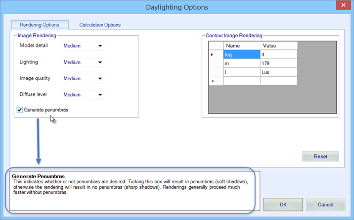
| Options
|
Opens
Daylighting Options dialog which
is used to set rendering and calculation options.
- Rendering
Options tab - Contains controls used to define aspects of both
image and contour renderings.
- Model
Detail - Sets the level of visual detail, and is used to
determining image sampling rate for rendered images.
- Lighting -
Specifies how much light varies over the surfaces. and is used to determine
what level of sampling is needed in the indirect calculation.
- Image
Quality - Sets the overall quality of rendered images.
- Diffuse Level -
Indicates how many diffuse reflections are important in the general lighting of
the zone.
- Generate
penumbras - When on, penumbras (soft shadows) are applied to
rendered images. When off, no penumbras are applied resulting in sharp shadows.
- Contour Image
Rendering - Displays several contour rendering options.
- Reset - Returns
all tab settings to defaults.
- Calculation
Options tab - Contains controls used to define calculation output
and accuracy options.
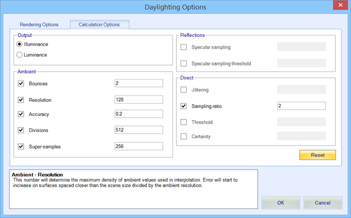
- Illuminance -
When on (default), sets calculation to produce illuminance values.
- Luminance -
When on, sets calculation to produce illuminance values.
- Bounces - When
on (default), sets the maximum number of diffuse bounces computed by the
indirect calculation.
- Resolution -
When on (default), sets the maximum density of ambient values used in
interpolation.
- Accuracy - When
on (default), approximates the error from indirect illuminance interpolation.
- Divisions -
When on (default), the error in the Monte Carlo calculation of indirect
illuminance is inversely proportional to the square root of the entered value.
- Super-samples -
When on (default), super-samples are applied onlt to the ambient divisions
which show a significant change.
- Specular
sampling - When on, sets the degree to which the highlights are
sampled for rough specular materials.
- Specular sampling
threshold - When on, sets the maximum fraction of reflection or
transmission, under which no specular sampling is performed.
- Jittering -
When on, sets the level of sampling points distribution.
- Sampling ratio
- When on (default), a light source is divided until the width of each sample
area divided by the distance to the illuminated point is below the ratio
entered here.
- Threshold -
When on, shadow testing is stopped when the potential contribution of at least
the next and at most all remaining light sources is less than the entered value
of the accumulated value.
- Certainty -
When on, a value of
1 guarantees the absolute accuracy
of the direct calculation is equal or better than the threshold value. A value
of
0 only insures all shadow lines
resulting in a contrast change greater than the threshold value are calculated.
- Reset - Returns
all tab settings to defaults.
- Integrated Help -
Help is provided in the field at the bottom of the dialog. Position the pointer
over the settings to enable help.
- OK - Saves
changes, applies them to the daylighting calculation, and closes the dialog.
- Cancel -
Discards changes, and closes the dialog.
|
| Start
|
Starts the calculation.
Note: Notifications
panel displays simulation status.
|